Arduino Oscilloscope
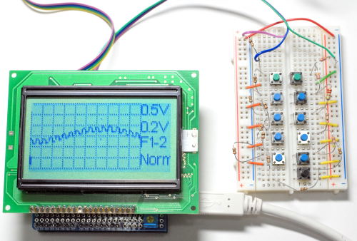
I have created a aimple Arduino Oscilloscope as above picture shows. Here is its summary. You can build your own!
| Number of channels | 2 |
| Input voltage | 0 to 5[V] |
| Input impedance | 10kohm?, depends on AVR |
| VOLTS/DIV | 1[V], 0.5[V], 0.2[V], 0.1[V], 50[mV] |
| TIME/DIV | 10[s], 5[s], 2[s], 1[s], 0.5[s], 0.2[s], 0.1[s], 50[ms], 20[ms], 10[ms], 5[ms], 2.3[ms] (4.3ksps), and 1.2[ms] (8.6ksps, samples only 1 channel) |
| Trigger mode | Auto, normal, scan, and one shot |
Operations are done with 11 switches. The following table shows how the switches are used.
| Menu 1 | Menu 2 | Menu 3 | |||
| Menu | Start/Hold | Menu | Start/Hold | Menu | Start/Hold |
| VOLTS/DIV (ch 1) | offset level (ch 1) | NORM/INV/OFF (ch 1) | |||
| VOLTS/DIV (ch 2) | offset level (ch 2) | NORM/INV/OFF (ch 2) | |||
| TIME/DIV | Trigger level | Trigger inputs (ch 1 or ch 2) | |||
| Trigger mode | Trigger edge | ||||
| Send | Send | Send | |||
The sketch depends on modified version of KS0108 Graphics Library which is introduced on Arduino: Playground. Note, you might have to change threshold voltages for switchs due to variations of registers' values. Also you might need to change the some constants depending on the voltage of Arduino's power source. Have fun!